Next: Transportation Infrastructure Overlay Up: Generic Arcology System Model Previous: Concept Development Contents
Models of structure specify how a system will accomplish its purpose. Typically, the system structure corresponds to collections of interconnected objects and subsystems, constrained by the environment within which the system must exist. The nature of each object and/or subsystem may be described by its attributes.
Our basic model consists of an overall package named GeneralHabitat, which contains base classes and three more packages to organize resources, reactions between entities, and a separate transportation infrastructure overlay on which this project will direct its focus.
The GeneralHabitat package contains a generalized resource queuing and transportation model of living support systems. A scenario is required to build up a model of a system by creating a hierarchy of cells that connect to each other via transportation network infrastructures. These cells would then begin to perform resource transactions between each other and resource reactions within themselves to simulate the daily operations of the system and observe it from different levels of detail, scaling from the individual to the city to the world. The transaction approach is well suited for implementation in a discrete event simulation.
Much of the model is static, such as monetary costs for resources or the structure of cells. This model is not intended to perform dynamic economic simulations or find ecological balances such as the equilibrium of birth and death rates of townspeople; those functions have been well studied. That said, the nature of the event-driven simulation framework makes it easy to patch in such functionality by manipulating variables or cleverly reorganizing the scenario outside of the simulation.
Instead, this model is merely intended to construct a glorified spreadsheet used to perform preliminary design and calculate rough benefits analysis on making way-of-life changes, quantifying answers to such questions as: ``how much energy might a city save if everyone installed more efficient light bulbs?'' or ``how much time and energy could we save if we staggered a city's work schedule to relieve rush hour congestion?''
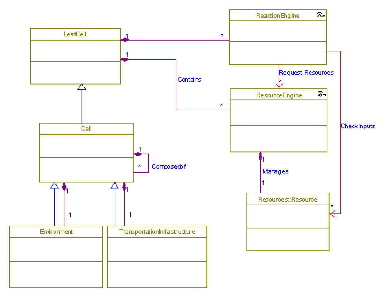
The GeneralClasses object model diagram (Rhapsody's internal name for a UML class diagram) depicts the base simulation classes and generally provides a template for completing the design of any simulation based on this framework. See Figure 2.6.
All object model diagrams following this pattern of classes constitute
scenario-specific use cases that highlight the use of the base
simulation classes. The specific purposes of each class are as follows:
The handling of resources and reactions are covered by the classes ReactionEngine, Resource, and ResourceEngine, respectively.
The ReactionEngine defines reactions that can occur within cells
to transform one set of resources into another set of resources. The
definition of the reaction governs changes to the quantities of inputs
and outputs, and balances them the same way a chemical reaction would be
balanced. Each resource engine keeps track of the flow of one resource
within a cell. This includes the input of resource from the environment,
trade of resources with other cells, internal reactions that transform
resources to and from other resources, and waste resource output back to
the environment. The resource engines are initialized to fire push / pull
transaction events at regular intervals. Pull transactions would offer
to exchange monetary resources for goods and services such as food or
electricity. Push transactions relate to the expulsion of waste, and
would end up in the immediate environment unless picked up by a
transportation system to take to, say, a waste processing plant
(represented by an industry) first.
Resources and reactions are not yet utilized in the current programming portion of this thesis, but the hooks have been left in place for performing studies with detailed resources accounting in the future.
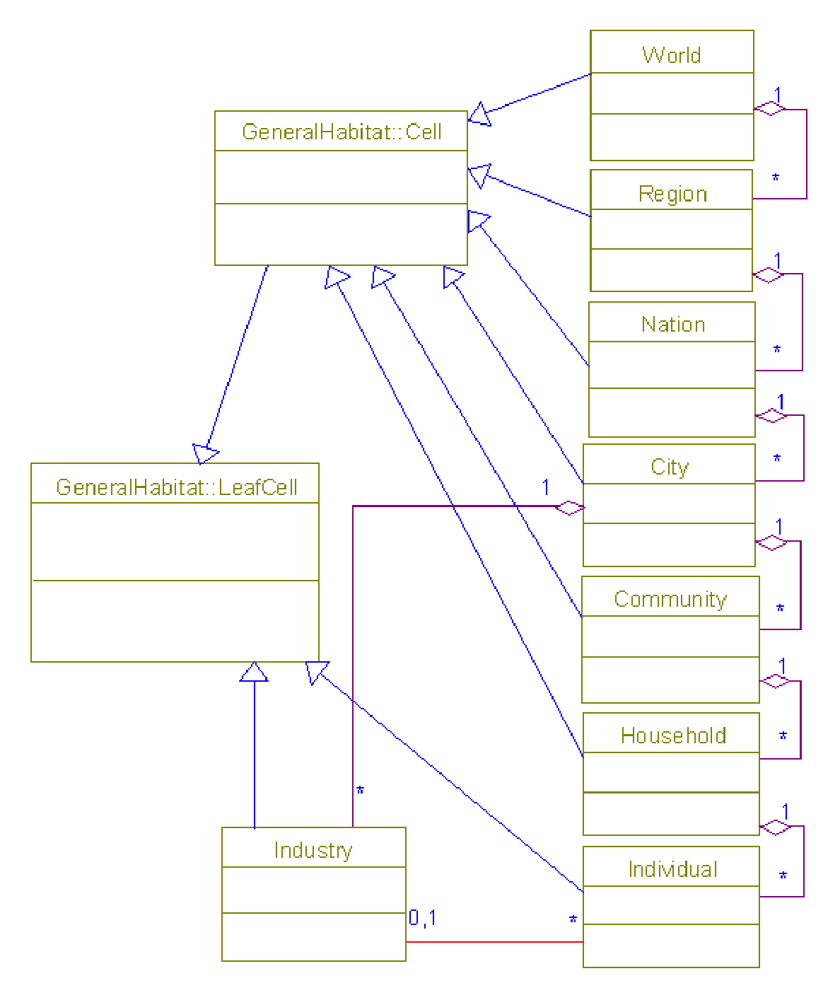
We model the area of interest by breaking it down into a hierarchy of cells and subcells that work at a different level of detail. There are essentially two types of units, parent nodes and leaf nodes, with the only distinction being that leaf nodes do not have any subcells. Levels of this hierarchy might correspond to jurisdictions of a society, as presented in the example CellTypes class diagram shown in Figure 2.7. It's important that all of the subcells add up exactly to form the parent cell, so in some cases, it would be necessary to define subcells that represent everything that might be left over after allocation into existing subcells. For example, the rural areas not part of a city would be lumped into a special residual ``City'' subcell to be included as part of a ``Nation''. Similarly, homeless people and vagrants would be lumped together into a special ``Household'' or ``Community'' subcell to be included as part of ``City'' data. This should be an acceptable practice, since these otherwise leftover units may tend to have similar characteristics.
The purpose of the example class hierarchy lined up along the right-hand side of Figure 2.7 might possibly be described as follows:
This thesis will focus on analyzing the people-mover component of a potential mass transit network.
Implementation Note.
From an implementation standpoint, the ``system model'' can be viewed
as a series of general-purpose templates, each represented as
(conceptual) classes and relationships among classes.
The latter translate to architectures in a software implementation.
UML diagrams of the Arcology model were created with I-Logix Rhapsody in C++ Development Edition. Work proceeded under the expectation that the code generation facilities for tools such as Rhapsody might someday be used to embed source code in the framework, and then compile and run a working executable. One of the side effects of using Rhapsody included some subtle differences in naming conventions, presumably used to simplify the merging of the standard OMG UML 1.1 specification with the practical realities of software engineering frameworks. Notably, Rhapsody uses ``Object Model Diagrams'' in place of both ``Class Diagrams'' and ``Instance Diagrams'', and prefixes class names with ``package'' names that get translated into programming language namespaces. Since this project deals with abstract models, we will almost always be referring to class diagrams rather than specific object instances.
Rowin Andruscavage 2007-05-22